


Grinding grain
shirley-calgary
17 years ago
Sort by:Oldest
Comments (6)
Related Stories
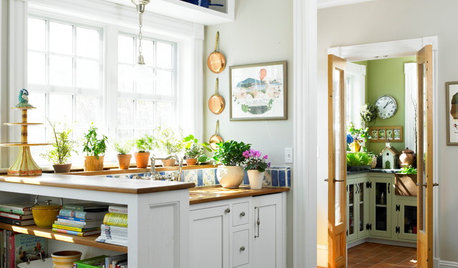
HEALTHY HOME12 Ways to Set Up Your Kitchen for Healthy Eating
Making smart food choices is easier when your kitchen is part of your support team
Full Story
SHOP HOUZZHouzz Products: Set Up Your Dream Coffee Station
Wouldn’t it be nice to have your own café that never closes? With these tools and accessories from the Houzz Products section, you can
Full Story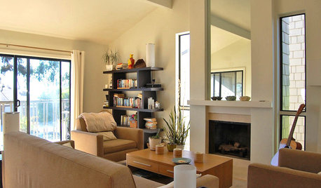
HOUZZ TOURSMy Houzz: Beachy Townhouse Getaway in San Diego
With a surfboard workshop in the garage and airiness all around, this townhome near the ocean celebrates sand-inspired style
Full Story
LIFEHow Do You Make Your Tea and Coffee in the Morning?
A morning cup is a must for many, and preparation comes in many guises. We look at coffee and tea habits across the Houzz community
Full Story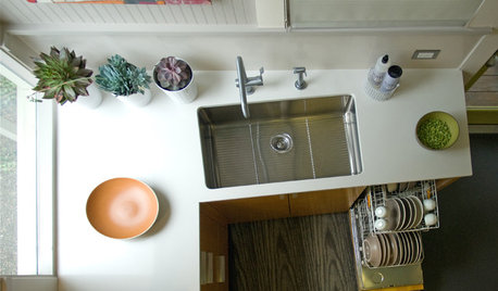
HOUSEKEEPINGHow to Fix a Stinky Garbage Disposal
No plumber’s fee or even a trip to the hardware store is required with these easy solutions
Full Story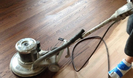
GREAT HOME PROJECTSWhat to Know Before Refinishing Your Floors
Learn costs and other important details about renewing a hardwood floor — and the one mistake you should avoid
Full Story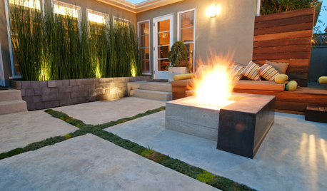
GREAT HOME PROJECTSHow to Tear Down That Concrete Patio
Clear the path for plantings or a more modern patio design by demolishing all or part of the concrete in your yard
Full Story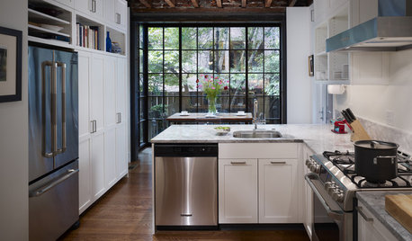
FEEL-GOOD HOME12 Very Useful Things I've Learned From Designers
These simple ideas can make life at home more efficient and enjoyable
Full Story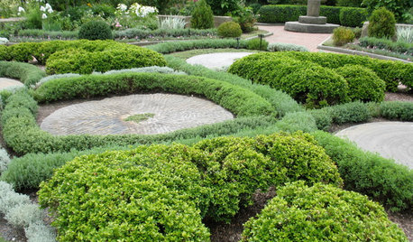
LANDSCAPE DESIGN5 Great Garden Uses for Granite Millstones
Give your yard character and history with a salvaged circular stone used as a patio, seat, fountain or focal point
Full Story
FLOORS6 Alternative Flooring Ideas to Kick Up Your Style
Rubber, cork, concrete and other materials are worthy options in lieu of hardwood or tile
Full StorySponsored
gran2
dannic_az
Related Professionals
Barrington Hills Landscape Architects & Landscape Designers · Forest Park Landscape Architects & Landscape Designers · Leawood Landscape Architects & Landscape Designers · Oconomowoc Landscape Architects & Landscape Designers · Seabrook Landscape Architects & Landscape Designers · Belmont Landscape Contractors · Corona Landscape Contractors · Holland Landscape Contractors · Shaker Heights Landscape Contractors · Teaneck Landscape Contractors · The Villages Landscape Contractors · Eastlake Landscape Contractors · Framingham Siding & Exteriors · Waukesha Siding & Exteriors · Wilmington Siding & Exteriorsjawnn
paulemorneault_yahoo_com
doninalaska
oregonwoodsmoke