


john deere 318 won't start
markwettig
10 years ago
Related Stories

REMODELING GUIDESYou Won't Believe What These Homeowners Found in Their Walls
From the banal to the downright bizarre, these uncovered artifacts may get you wondering what may be hidden in your own home
Full Story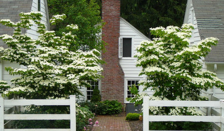
TREES7 Deer-Resistant Flowering Trees to Plant this Fall
If you live in a neighborhood with roaming deer, consider these beautiful trees that won't tempt hungry guests
Full Story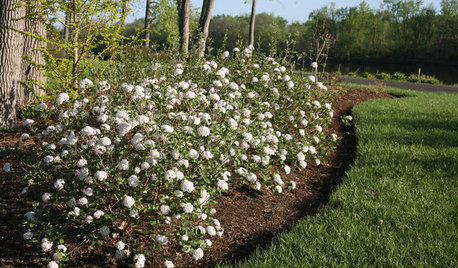
FALL GARDENING9 Deer-Resistant Flowering Shrubs to Plant This Fall
These exquisite shrubs will attract your attention but won’t tempt the deer that roam your neighborhood at night
Full Story
DECLUTTERING5 Ways to Jump-Start a Whole-House Decluttering Effort
If the piles of paperwork and jampacked closets have you feeling like a deer in the headlights, take a deep breath and a baby step
Full Story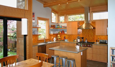
CONTRACTOR TIPS10 Things to Discuss With Your Contractor Before Work Starts
Have a meeting a week before hammers and shovels fly to make sure everyone’s on the same page
Full Story
GARDENING GUIDESOh, Deer! 10 Native Flowers That Stand Up to the Herds
Keeping a garden amid hungry deer can be hard, but these plants should fare well
Full Story
ARCHITECTURESee the Daring Experimentalist Who Won 2013's Pritzker Prize
Architecture's highest honor goes to someone with a diverse and complex body of work and a never-satisfied mind-set
Full Story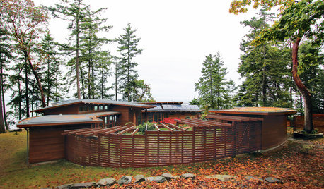
FENCES AND GATESA Deer Fence Can Be Decorative as Well as Protective
You need a monster-size fence to shelter your garden from deer, but it doesn’t have to look like a monstrosity
Full Story
MOST POPULARHow to Start a Cool-Season Vegetable Garden
Late summer and late winter are good times to plan and plant cool-season crops like salad greens, spinach, beets, carrots and peas
Full Story
GARDENING FOR BUTTERFLIESA Quick-Start Guide to Bird-Watching for Fun and Learning
Set out some seed and grab your field guide. Bird-watching is an easy, entertaining and educational activity for the whole family
Full Story
Sponsored
bill_kapaun
markwettigOriginal Author
Related Professionals
Fort Lee Landscape Architects & Landscape Designers · Jennings Landscape Architects & Landscape Designers · Mitchellville Landscape Architects & Landscape Designers · Forest City Landscape Architects & Landscape Designers · Washington Landscape Architects & Landscape Designers · Milford Landscape Contractors · Annandale Landscape Contractors · Galveston Landscape Contractors · Ramsey Landscape Contractors · Tavares Landscape Contractors · Wichita Window Contractors · Plainview Window Contractors · Tucker Window Contractors · West Springfield Window Contractors · Hialeah Gardens Window Contractorsbill_kapaun
markwettigOriginal Author
bill_kapaun
markwettigOriginal Author
bill_kapaun
markwettigOriginal Author
bill_kapaun
markwettigOriginal Author
Bob Yingling
Bob Yingling